The goal of this semester’s project is to give continuance to concepts from previous engineering projects while using some of the technologies previously developed to create a more intuitive and robust design. The 6WD Intelligent Self-Guided/RC Rover is a preliminary version of a conceptual heavy-duty, 6-Wheel Drive mini robot mainly designed to assist humans, and can be adapted for various tasks and applications. It features a remote control and obstacle detection system—using the ultrasonic module that was created last semester— and can be adapted for search and rescue operations, law enforcement assistance and investigation. Such tasks would include retrieving objects in confined spaces, handling dangerous materials, assisting people trapped in caves, collecting evidence, and using weapons to neutralize threats.
PROJECT OVERVIEW
The 6WD Intelligent Self-Guided/RC Rover is an experimental prototype, developed based on the concepts from previous RC projects. It implements many of the important devices developed in the previous project, such as the USM-16CH 6-channel ultrasonic module and the DMD14A dual motor driver. The rover is built on a six-wheel-drive platform using a total of six motor drivers (one for each wheel). The DMD14A is a low current dual motor driver developed exclusively for my previous RC project (Collision Assist RC Car with 6-Channel Ultrasonic Module). However, it was a perfect fit for this project as well. The ultrasonic module (USM-16CH) was also part of the previous design project. It was created exclusively to replace an old infrared system from my very first engineering project, but can also be used in most projects that need ultrasonic sensors, like this one. The system also uses the RF24L01 module to transmit and receive, which is the same radio communication method used in the previous projects.
The key difference between this project and previous ones is that this project uses standalone ATMega328P microcontroller chips rather than ‘ready-to-use’ Arduino boards. A total of four microcontroller chips are utilized in this project, three on the receiver board and one in the remote control. The reason I decided to use standalone microcontrollers instead of Arduino is because I wanted to have full control over my project. I also wanted my board to have a unique design which is not being used anywhere else. The only drawback of this, is that it involves the inclusion of extra components to the circuit, which can add more complexity to the project.
One of the greatest challenges I faced by using microcontrollers chips was to learn how to program them. It took me some trials and errors and a good amount of time to figure that out. The ATMega328P can be programmed using either the in-System Programming (ISP) or the USB-to-serial method (using FTDI interfaces). Although the most recommended, I was not very successful using the FTDI method. This is because this method does not work right out of the box and normally requires strict plugin configuration. I initially tried to use FTDI, but after multiple unsuccessful attempts, I decided to switch to the ISP programming method. To facilitate the process, I created an ISP programmer using an Arduino Nano, which worked as expected. However, this required me to redesign the original circuit boards from scratch to be compatible with the new ISP programmer.
PLANNING AND DESIGN

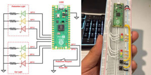
Figure 1. Block diagram illustrating the input and output connections of the rx module.
The block diagram on Figure 1 was created to illustrate the connections between the three chips and external components before the actual circuit diagram was designed. It shows the wiring between the microcontrollers, as well as the inputs and outputs to and from external components, such as sensors, switches, motors, and lights. To help better understand how the signal flows within the circuit, the direction on each connection is represented by arrows. The implementation of such a comprehensive block diagram made the circuit design much easier and simplified the coding process for each microcontroller.
With the block diagram in hand, the next step was to create the circuit diagram and the PCB layouts for the project. Similar to the previous projects, this step was done on KiCad—an open source EDA software used for electronic schematic and board design. In addition to the main board, which contains most of the components, the project also includes separate boards for the power supply, ultrasonic modules, and an extension board where the power switches and the programmer’s connectors are located.
The final step of the hardware design process was to design the aluminum base and cover for the Rover. This step was probably the most challenging, as it required precise measurements to be taken, where every millimeter was crucial. The whole design process was done using a combination of Adobe Illustrator and TinkerCad. In addition, an online cutting service was used to precisely cut the aluminum sheets. The screenshots of the Adobe Illustrator’s 2D files, showing the design of the base and cover along with all measurements taken can be found at the end of this section. The following is the list of the main hardware involved for the functionality of the Rover project:
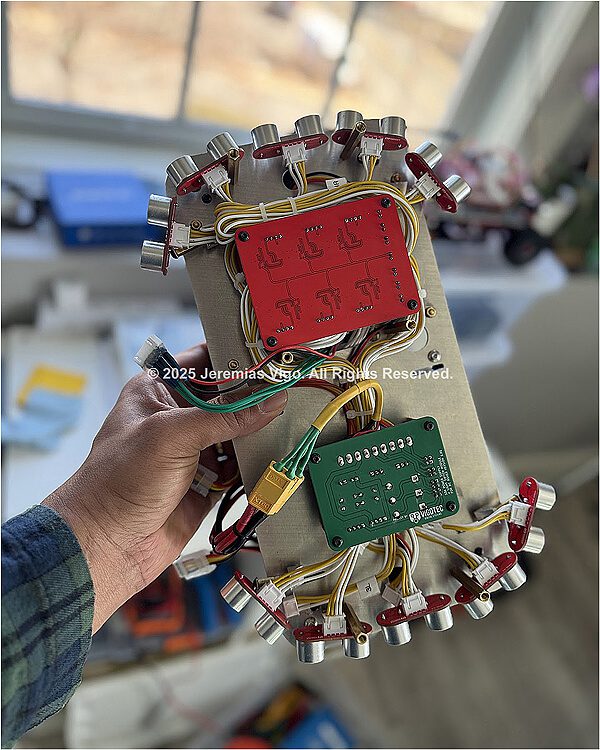
Rx Control Module – The rx control module (receiver) is the main board of the Rover. This is the section where all three microcontrollers are located and is responsible for receiving commands from the tx control module over radio transmission and translating these commands into electrical signals to control the Rover’s movement. This is also the section where the motor drivers are located along with all input and output connections to the other boards. There are six DC motors which are controlled by six individual motor drivers. The motor drivers of choice were the dual motor drivers, DMD14A, designed as part of the previous engineering project. The radio communication between the tx and the rx modules is made over two nRF24L01 modules (one located at the remote control and the other at the rx control module). Figure 2 is a screenshot of the rx control module’s electrical diagram, while Table 1 contains a list of all components used in this module.
As mentioned above, the rx control modules use three ATMega328P microcontrollers. These chips are the same type as the ones used in Arduino Nano or Uno, with the only difference that the Arduino has its own integrated programmer and does not require an external voltage regulator. However, using standalone chips certainly makes the project look more intuitive and professional.

Figure 2. Complete schematic of the rx control module (receiver board)
Table 1. List of all components used in the rx module
| Qty | Reference | Value |
| 6 | C1,C2,C3,C4,C9,C11 | 22pF |
| 2 | C5,C6 | 100nF |
| 1 | C7 | 1uF |
| 1 | C8 | 330uF |
| 1 | C10 | 47uF |
| 3 | D1,D2,D3 | LED |
| 4 | R1,R2,R9,R10 | 220R |
| 3 | R3,R8,R11 | 10k |
| 5 | R4,R5,R6,R7,R12 | 330R |
| 3 | SW1,SW2,SW3 | Toggle Switches |
| 3 | U1,U2,U3 | ATmega328-P |
| 1 | U4 | L78L33 |
| 1 | U5 | L7805 |
| 1 | U6 | NRF24L01 |
| 3 | Y1,Y2,Y3 | 16 MHz Crystal |
Tx Control Module – The Tx control module (transmitter) is the Rover’s remote control. It uses the same microcontroller that is used in the Rx module (ATMega328P). The microcontroller is programmed to collect data from both joysticks and switches and send it to the Rx module remotely, using the nRF24L01 module. The complete electrical schematic is shown on Figure 3.

Figure 3. Electronic schematic of the tx control module (remote control)
Table 2. List of components used in the tx module
| Qty | Reference | Value |
| 2 | C1,C2 | 22pF |
| 2 | C4,C5 | 100nF |
| 1 | C6 | 1uF |
| 1 | C7 | 330uF |
| 1 | C8 | 47uF |
| 3 | D1,D2,D3 | LED |
| 1 | J3 | Joystick 1 |
| 1 | J4 | Joystick 2 |
| 1 | R1 | 10k |
| 3 | R2,R6,R7 | 1K |
| 3 | R3,R4,R5 | 330R |
| 3 | SW1,SW2,SW3,SW4 | Toggle Switches |
| 1 | U1 | ATmega328-P |
| 1 | U2 | L78L33 |
| 1 | U3 | L7805 |
| 1 | U4 | NRF24L01 |
| 1 | Y1 | 16 MHz Crystal |
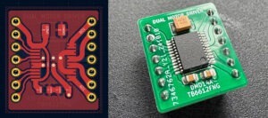
Motor Drivers – The motor drivers used to control the DC motors are the DMD14A (which stands for Dual Motor Driver/14 pins/Active). They are dual motor drivers and were designed as part of a previous engineering project, so I decided not to include their schematic in this technical report. The “Active” term indicates that the driver receives a constant 5V on its standby pin, making it enable the whole time while the system is on. The motor drivers use the TB6612FNG microchip from Toshiba, which is made of MOSFET-based H-bridges, compared to BJT-based H-bridges used in the older drivers; this makes it more efficient and more reliable than the popular L298N. In addition, while most small size motor drivers use 16 pins, this model uses only 14, which also makes it more compact than most motor drivers in the market.
Ultrasonic module – The 6-channel ultrasonic module (USM16-6CH) was also developed as part of the previous project, so their schematic is not included in this technical report. The module consists of six sensors and a control module integrated into a single board managing all six channels independently. The control module works by sending and receiving ultrasonic signals through the sensors and then translating these signals into electrical voltage and sending them to the microcontrollers. The ultrasonic module is based on the RCWL-9610, a single chip microcomputer, responsible for generating and processing the ultrasonic signals it receives.
Power Supply – The power supply designed for the Rover uses a very straightforward concept. As it was previously mentioned, the original power supply designed for the project did not work due to low power problems. The schematic on Figure 4 shows the new power supply that was created as part of the problem correction and replaces the original design.

Figure 4. Schematic of the power supply (version 2) used for the project.
Table 3. List of components used in the power supply
| Qty | Reference | Value |
| 1 | C1 | 47uF |
| 1 | C2 | 22uF |
| 3 | D1,D2,D3 | 1N5404 |
| 2 | Q1,Q2 | IRLIZ44N |
| 2 | R1,R4 | 10K |
| 2 | R2,R3 | 39K |
The new design consists of only a few components compared to the original design which had a more complex circuit. As we can notice on Figure 4, the voltage regulator section is basically consistent with 3 series diodes, which takes advantage of their higher voltage drop and power. In this case, I chose the 1N5404 which can support a higher forward current of up 3A and a voltage drop of 1.2V. The reason I needed such a high voltage drop was to be able to produce different voltage options, which could be later selected using a jump switch. For instance, this power supply can produce up to 3 different voltages, 11.2V (battery limit), 10V, and 8.8V. This means we have 3 different voltage levels that we can choose from for the Rover to operate.
In addition, the super-lights control circuit was integrated into the power supply’s board due to space constraints. This was not part of the original design, so I took advantage of the extra space on the power supply’s board to include it. It uses two Single N-Channel Power MOSFET N-Type transistors to switch the lights on or off.
Aluminum Base and Cover – The final step of the hardware design process was to design the aluminum base and cover for the Rover. This step was probably the most challenging, as it required precise measurements to be taken where every millimeter was crucial. The whole design process was done using a combination of Adobe Illustrator and TinkerCad. In addition, an online cutting service was used to precisely cut the aluminum sheets. Figure 5 shows the screenshots of the Adobe Illustrator’s 2D files, showing the design of the (a) base and (b) cover, along with all measurements taken.

Figure 5. Aluminum sheets (base and cover) as drawn/measured in Adobe Illustrator.
ISP Programmer – The ISP programmer was designed as part of the challenge I faced while trying to program the microcontrollers. For some reason I was not very successful using the popular FTDI method. As mentioned previously, there are other methods which the ATMega328P can be programmed with, and one of them is the in-System Programming (ISP). Because of this, to move forward and avoid wasting time, I created an ISP programmer using an Arduino Nano, which worked as expected. The schematic in Figure 6 shows that the programmer only requires a few components, which is very convenient.

Figure 6. Schematic of the ISP programmer
Table 4. List of components used in the ISP programmer
| Qty | Reference | Value |
| 1 | A1 | Arduino Nano v3 |
| 1 | D1 | LED (Programming) |
| 1 | D2 | LED (Error) |
| 2 | R1,R2 | 220R |
TECHNICAL SPECIFICATIONS
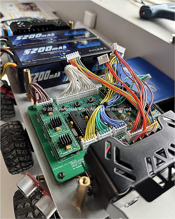
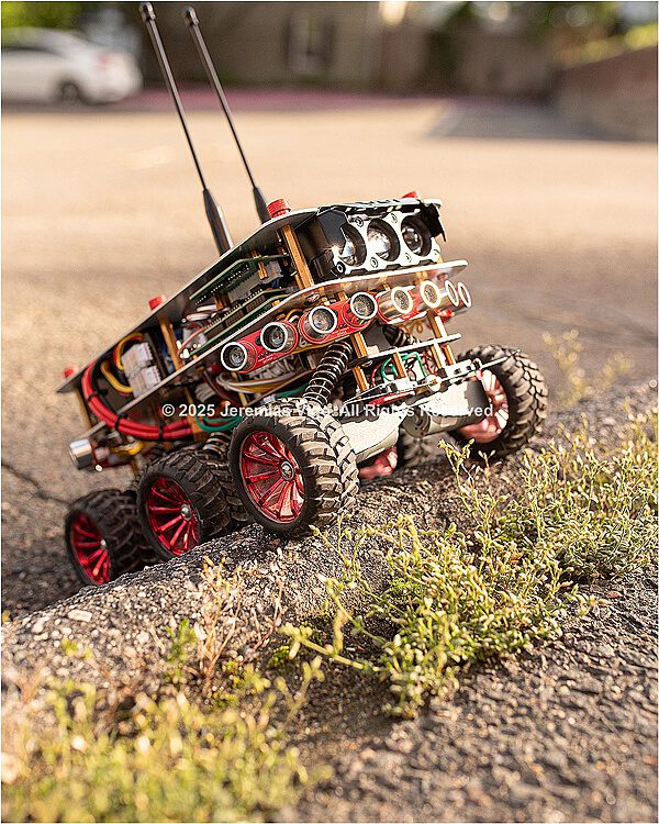
Once the project was fully completed, some measurements were taken and extra data regarding the specifications of the rover were generated. Figure 7 is the actual photograph of the rover and Table 5 shows its main physical and electrical specifications.

Figure 7. Actual photograph of the 6WD Intelligent Self-Guided/RC Rover
Table 5. Basic physical and electrical specifications
| Physical aspects | ||
| Length (cm) | 33.02 cm | |
| Width (cm) | 22.86 cm | |
| Height (with antenna) | 36.85 cm | |
| Height (without antenna) | 17.70 cm | |
| Floor area | 755 cm2 | |
| Total weight (Kg) | 3.27 Kg | |
| Motors’ speed | 77 RPM | |
| Rover’s speed | 915 meters/hour | |
| Electrical specifications | ||
| Operating voltage | Maximum voltage | 11.2V |
| Minimum voltage | 7.2V | |
| Operating current | All motors / Sensors off / Light off | 380mA |
| All motors / Sensors on / Light off | 410mA | |
| All motors / Sensors on / Light on | 1A | |
| Neutral / Sensors on / Light off | 127mA | |
| Neutral / Sensors off / Light off | 85mA | |
| Stall current (approximately) | ~2.8A | |
PROBLEMS AND TROUBLESHOOTING
Once everything had arrived and all components were on the table, the wiring process was very straightforward. Except for the ultrasonic modules—which were based on Surface Mount Devices (SMD)— the majority of the components were Through Hole Technology (THT) type. This made soldering these components on the PCBs one of the easiest tasks of all. However, it took me a few weeks before getting everything up and running due to some problems encountered along the building process. Of the challenges encountered during the testing process, the most significant ones are as follows:
- Insufficient power problem – This was a design related problem presented immediately after the assembling. While the system was turning on normally, the motors were responding erratically to the remote control’s commands only for a few seconds before stopping responding completely. Further investigation concluded that the problem was due to the lower current draw by the power supply. A new power supply was designed and the issue was successfully addressed.
- Bump sensor conflict – The left and right microcontrollers initially presented programming problems which prevented successful uploading of codes. The problem occurred immediately after the bump sensors were installed (note that these sensors were not originally planned for this design). Further observations concluded that the sensors occupied two pins that were already being used by the ISP programmer. Rewiring was not necessary in this case. However, programming these microcontrollers now requires pressing and holding the bump sensor switches for a few seconds.
- Missing data line – A data line connecting the center and the side (left and right) microcontrollers were missing from the design. This prevented the center controller from sharing the mode status to the side controllers, which caused the side controllers not responding to the self-guided enable signal. The issue was fixed successfully by soldering a new wire from pin 27 of the side controllers to pins 25 and 26 respectively of the center controller.
- Front sensor not working – At first I thought this was a code related problem. Further code testing shows that the code was ok. The front transducer was also tested and nothing wrong was found with it. However, after some troubleshooting, I found that channel 6 of the ultrasonic module was not working. Fortunately, there was an extra channel available which replaced channel 6 and everything worked fine.
- Floating pin – While testing the remote control, I found that one of the functions responsible for setting the two modes (self-guided/manual) was not operating properly. At first I thought it could be something related to the switch, but after some investigations I found that the problem was due to a missing pull-down resistor at pin #6 of the microcontroller. The problem was easily solved by connecting a 1KΩ resistor between the pin and the ground of the circuit.
PURPOSE AND APPLICATIONS
The Intelligent Self-Guided RC Rover was designed to be a heavy-duty, 6-Wheel Drive mini robot that can be adapted for multiple tasks and applications. While still considered a conceptual prototype, the idea was to create something that could be used to assist humans in various ways. Its remote control functionality and obstacle detection system make it ideal for ground-level operations, particularly in search and rescue and law enforcement. The following are the most common applications it can be adapted for:
Search and rescue:
- Retrieve objects from places where humans cannot access.
- Perform dangerous tasks such as disarming a bomb or disposing a hazardous material.
- Provide assistance to people trapped in caves or mines while they wait for rescue.
Law enforcement and investigation:
- Collect physical evidence in dangerous or confined spaces.
- Can be adapted with a hidden camera to secretly capture video/photo evidence.
- Find the best position to neutralize a threat using pre-mounted weapons.
CONCLUSION
There are many concepts involved in this project, which makes it quite difficult to focus on just one. Overall, we can conclude that the project exceeded most of the initial expectations —despite some issues encountered throughout the design process, which was expected. The project successfully implements some of the important components developed as part of previous engineering projects, such as the USM16-6CH ultrasonic module and the DMD14A motor driver. The ability to use these components is one of the aspects of this project that makes it so unique. Furthermore, the ability to use standalone microcontrollers instead of Arduino is another very significant aspect of this project, especially due to its adaptability to different applications.


REFERENCES
- Alexander, Charles K., Sadiku, Matthew N. O. Fundamentals of Electric Circuits — Sixth edition, Published by McGraw-Hill Education, New York, 2017
- Atmel Corporation. Atmel-42735A-ATmega328/P_Datasheet_Summary-06/2016. Microchip Technology Inc, microchip.com/en-us
- Arduino IDE. Open-source Arduino Software. Arduino S.r.l. https://www.arduino.cc/en/software/
- Components101, Electronic Resources for Engineers. ATMega328P Microcontroller Pin Configuration. https://components101.com/microcontrollers/atmega328p-pinout-features-datasheet
- Draw.io. Open source online diagram software. JGraph Ltd, Artisans’ House, 7 Queensbridge, NN4 7BF, Northampton, England. Company #04051179. https://app.diagrams.net/
- KiCad EDA. Schematic Capture & PCB Design Software, KiCad Developers Team, 1992-2024, https://www.kicad.org/ Multisim Online Software. Web-base electrical simulation software. National Instruments Corp ©, 2025, https://www.multisim.com/