Over the past few months, I’ve been working on creating electronics components in support of my engineering projects, specifically those projects that involve precise motor control. From my previous designs, like the Collision Assist Remote Control Car and the 6WD Intelligent Self-Guided Rover, I realized that a compact and more efficient motor driver was essential to handle the demands of these systems. That’s when the DMD14A Motor Driver was developed.
The module itself is built using the Toshiba TB6612FNG dual H-bridge driver IC, which is a great option when it comes to motor control in a small form factor. It is designed for integration into robotics, automation, and other embedded systems where space constraints, efficiency, and performance are critical.
ELECTRICAL DESIGN
The schematic, shown on Figure #, is the complete electrical diagram of the DMD14A Motor Driver. It highlights the wiring of the TB6612FNG IC along with each component that was used in the motor driver. It also shows each of the pins that are used to connect with external components, power supplies, and microcontrollers such as Arduino.

Figure 1 — Full schematic of the DMD14A Motor Driver.
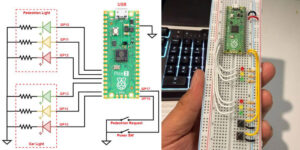
The diagram below, shown on Figure 2, is the setup method used to connect the motor driver to the Arduino. As you can see, the inputs and outputs of the driver are connected in parallel. This setup not only allows more power to the motor, but also makes the motor driver more stable by sharing the work between its two channels. In addition to the power connections, the motor driver takes three pins on the Arduino: D4, D5, and D6. While D4 and D5 are digital outputs that send high and low signals to the motor driver for forward/reverse, D6 is the PWM output responsible for controlling the speed of the car. It is important to note that the 5V power supply in the diagram is only used to power the driver itself and not the motor. However, the VMOT pin of the motor driver is connected directly to the battery (~7.5V) and is used to power the motor.

Figure 2. Wiring diagram of the DMD14A.
PCB LAYOUT
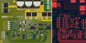
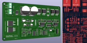
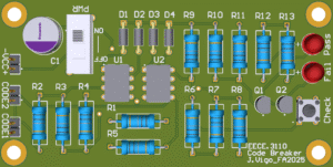
The DMD14A was developed using careful consideration of power distribution, signal integrity, and thermal management. As we notice on Figure 3, the PCB layout was optimized to reduce interference between motor control lines and high-current traces were reinforced to support continuous operation.

Figure 3 — PCB layout and a 3D simulation from KiCad of the DMD14A Motor Driver.
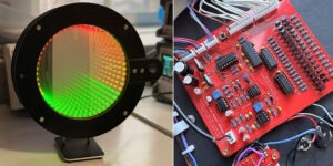
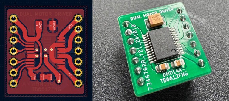
The initial prototypes, shown on Figure 4, were fabricated, assembled, and tested followed by validation under various load conditions. For a more intense operation at higher currents, heatsinks were added to ensure safe thermal performance.

Figure 4 — Pictures of the actual prototypes of the DMD14A module.
TECHNICAL SPECIFICATIONS
Below on Table 1, we can find all technical specifications of the motor driver.
Table 1 — Technical specifications
| Parameter | Specification |
| Driver IC | Toshiba TB6612FNG (Dual H-Bridge Motor Driver) |
| Motor Supply Voltage | 4.5V – 13.5V |
| Logic Supply Voltage | 2.7V – 5.5V |
| Continuous Current | Up to 1.2A per channel |
| Peak Current | 3.2A (with adequate heat dissipation) |
| Control Interface | PWM + Directional Inputs (AIN1, AIN2, BIN1, BIN2) |
| Outputs | Dual Motor Channels (A01/A02, B01/B02) |
| Package Dimensions | Compact PCB, designed for robotics integration |
APPLICATIONS
The DMD14A is well-suited for:
- Autonomous vehicles – enabling compact control modules for differential drive systems.
- Robotics platforms – providing efficient power handling for multi-motor configurations such as six-wheel rovers.
- RC systems – where both compactness and efficiency are critical to performance.
This module has already been successfully implemented in both my previous automated projects (Collision Assist RC Car and the 6WD Rover ) and has demonstrated high reliability and efficiency. Figure 5 shows a photo of the rover’s main board with six DMD14A motor drivers (some are hidden behind the wires) embedded in it.

Figure 5 — Photo of the rover’s main board using six DMD14A motor drivers.
CONCLUSION
The DMD14A Motor Driver represents a significant step toward more efficient and reliable motor control solutions for embedded systems. Its compact design, combined with its robust electrical performance, makes it a great choice for robotics engineering and automated embedded systems.