In continuation to our previous engineering project (in which we created an interesting version of a remote control car), we decided to build an upgraded version, but this time, using a slightly different method. Both projects use similar mechanical and electronics concepts, but the main difference lies in the type of sensors they use. Our current design includes the development of a 6-channel ultrasonic module—which replaced the old infrared sensors from the previous version—and a very unique version of motor driver. Here, we have highlighted some of the important steps used throughout the creation of this project, as well as analytical data generated along the development process. In addition, we emphasized some important information such as how the system works, applications, and how it would help solving everyday problems.
PROJECT OVERVIEW
For our engineering project this semester, we built a collision assist remote control car using a 6-channel ultrasonic module created specifically for our project. While the car uses the same mechanical parts as the previous version (such as the chassis, wheels, servo, and DC motor), the electronic hardware was completely modified to support the new ultrasonic system. In addition to the ultrasonic module, the project also introduced new, redesigned Rx and Tx control modules, as well as a custom motor driver designed specifically for the project.
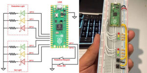
The Tx control module (transmitter) is the remote control for the car. It is exactly the same model used in the previous project, with the only difference being that it uses a different radio frequency so that one does not interfere with the other. The microcontroller, often called the “master microcontroller”, is programmed to collect data from the right and left joysticks and send it to the receiver (Rx) wirelessly, using the nRF24L01 module. A unique feature of the transmitter is that it requires minimal components to operate: an Arduino, an RF24 module, two joysticks, a voltage regulator, three capacitors, a 7.5 V battery and, of course, a bunch of jumper wires. A complete schematic of the tx control module along with a partial sketch of the code used for the program is shown in Appendix A.
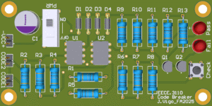
On the other hand, the Rx control module (receiver) is the main board of the car. This is the section where the “slave” microcontroller is located and is responsible for receiving commands from the tx control module over radio communication. The rx control module is also responsible for controlling the servo and the DC motor. The DC motor is powered by the motor driver (mentioned next), which was designed uniquely for this car, such that the car will not operate with another motor driver but its own. The microcontroller of choice for both receiver and transmitter is the Arduino Nano version 3, as it is more compact, saving space for other components and making it useful for other small design projects. The radio communication between the tx and the rx module is transmitted over two nRF24L01 modules. Figure 1(a) shows a high contrast picture of the rx control module’s PCB design, while Figure 1(b) shows a simulated version created on Kicad. The actual photos and the electrical diagram of this module is shown in Appendix A. A partial sketch of the code used to program the board’s microcontroller is also in Appendix A.

Figure 1. PCB design of the Rx control module.
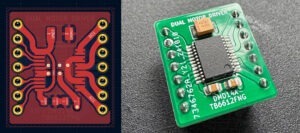
The motor driver we used to control the DC motor is the DMD14A (which stands for Dual Motor Driver/14 pins/Active). It is a dual motor driver and was designed specifically for this project. The “Active” term indicates that the driver receives a constant 5V on its standby pin, making it active all times while the system is on. The motor driver uses the TB6612FNG microchip from Toshiba, which is made of MOSFET-based H-bridges, instead of BJT-based H-bridges used in older drivers; this makes it more efficient and more reliable than the popular L298N. While most small size motor drivers use 16 pins, our model uses only 14, which makes it smaller than most motor drivers in the market.
The diagram below shows the setup method used to connect the motor driver to the Arduino. As you can see, the inputs and outputs of the driver are connected in parallel. This setup not only allows more power to the motor, but also makes the motor driver more stable by sharing the work between its two channels. In addition to the power connections, the motor driver takes three pins on the Arduino: D4, D5, and D6. While D4 and D5 are digital outputs that send high and low signals to the motor driver for forward/reverse, D6 is the PWM output responsible for controlling the speed of the car. It is important to note that the 5V power supply in the diagram is only used to power the driver itself and not the motor. However, the VMOT pin of the motor driver is connected directly to the battery (~7.5V) and is used to power the motor.

Figure 2. Wiring diagram of the DMD14A.
The following are some features and specifications of the DMD14A:
- Dual-H-bridge motor driver: controls two DC motors or one bipolar stepper motor
- Motor voltage (VMOT): 4.5V to 13.5V
- Output current maximum: 3A peak per channel
- Output current continuous: 1A per channel (2A if connected in parallel)
- Maximum PWM frequency: 100 kHz
- Built-in thermal shutdown circuit
- Filtering capacitors on both supply lines
- Reverse-power protection on the motor supply
Figure 2 shows the complete schematic of the DMD14A motor driver. The actual pictures of the driver itself can be found in Appendix A.

Figure 3. Electrical schematic of the DMD14A dual motor driver.
Similarly, the 6-channel ultrasonic module (USM16-6CH) was developed specifically for this project and is composed of six sensors (transducers) and a control module integrated into a single board containing the necessary components for all six channels. The control module has the role of decoding the ultrasonic signals received by the transducers and sending them to the microcontroller. Primarily, the idea was to use the old car and replace its old infrared system with the new ultrasonic module. However, we decided to keep the old project untouched and build everything from scratch.
The main idea of developing our own ultrasonic module rather than using the ones already existing in the market is to avoid having electronic components spreaded around the car and to minimize the problem of power disconnections. We thought that having everything integrated into one single board would make things simpler, provide more stability to the system, and therefore, make installation and troubleshooting much easier. However, achieving this design was not an easy process. It was not something that was simply copied and pasted from somewhere else, but the result of extensive research with many failed attempts.

Figure 4. Electrical schematic of a single channel of the USM16-6CH.
The schematic on the figure above is the electrical diagram of a single channel from the USM16-6CH. As we may notice, the module uses the RCWL-9610, a single chip microcomputer module, that processes the ultrasonic signals between the sensors and the Arduino. On Table 1 we have listed a brief summary specification of the RCWL-9610 (translated from its Chinese datasheet).
Table 1. Input/output configuration switch.
| Parameter name | Remark | Minimum value | Typical value | Maximum value | Unit |
| Operating voltage | 2.8 | 5.5 | V | ||
| Operating current | 2 | 3 | mA | ||
| Detection distance | Flat wall | 350 | 400 | 600 | cm |
| Working frequency | 40 | KHz | |||
| Blind spot | Random value in blind zone | 2 | 3 | cm | |
| Detection accuracy | same temperature | ± 2 | % | ||
| Resolution | theory | 1 | mm | ||
| Detection angle | Maximum Direction Angle | ± 15 | ± 20 | ||
| Measuring cycle time | GPIO / 1-WIRE | 70 | mS | ||
| Measuring cycle time | UART / I2C | 120 | mS | ||
| Output interface mode | GPIO / UART/ I2C/ 1-WIRE | ||||
| Storage temperature | -50 | 100 | ℃ | ||
| Operating temperature | -40 | 90 | ℃ | ||
| Package size | SOP16 | ||||
The electrical schematic and PCB design for the ultrasonic module were created on Kicad. Similar to the other boards, once all the electrical schematics were finalized and the boards were designed, the fabrication files were exported and the PCB was printed through an online service of preference. Using the same techniques and services as the previous projects made the process much easier, since everything was already set up. However, one of the major challenges about this new project is that it involved working with Surface Mount Devices (SMD), while the previous boards were built solely using Through-Hole Technology (THT). As we may notice below on Figure 5(b), all the components used for the ultrasonic module were SMD-based components—except for the connectors.
Figure 5 (a) is a high contrast picture of the ultrasonic module’s PCB, highlighting all the tracks and pads of the board. Figure 5 (b), on the other hand, shows the same board with the SMD components in place.

Figure 5. PCB design of the USM16-6CH.
PURPOSE AND APPLICATIONS
As mentioned, this design project was primarily developed with the objective of giving continuation to a previous project—where we created a remote-control car with infrared collision assistance. The reason we decided to work on quite a similar project is because there was a flaw with the previous design. Infrared sensors are sensitive to light which negatively affected the behavior of our previous model in daylight. We tried a few solutions to correct the problem, but none worked. So, it was motivated on how to address this issue that we decided to move forward and develop a more improved version, in which we chose ultrasonic sensors instead of infrared.
Although the whole project involved the development of three major hardware components, the core of this project is still the USM16-6CH ultrasonic module. This was undoubtedly the most challenging part of the project, but at the same time, the most rewarding one as well. This compact, newly designed board was designed in such a way that it can be easily customized for any other purpose. It can be adapted to any other electronic devices such as remote control cars, drones, robots, and most specifically those that use assist or automation.
While ultrasonic sensors are not new, the USM16-6CH is very unique in terms of design and application and could be the solution to many problems affecting sensor-based electronics. These electronics are easily affected by sensitivity related problems which often lead to malfunction and accidents. The main issue with these devices is that most of them are prone to environmental interferences such as light, heat, radio frequencies, electromagnetic fields, etc. Our previous project, for example—in which we chose infrared as the collision assistant—was greatly affected by light sensitivity issues that prevented it from working properly in daylight. This is the main reason why we felt the need to develop a project that could address these issues.

Figure 6. Design comparison between the HC-SR04 (a) and the USM16-6CH (b).
There are many ultrasonic devices in the market today that can be used as temporary workarounds in small design projects, such as the popular HC-SR04, shown on Figure 6(a). They are usually low cost and can do the job most of the time. However, these devices are not always the best solution and are often prone to problems. One of the main problems faced by these devices is mostly related to power connection issues. For example, the power cable to the transceiver can easily break (due to device’s movement) leading to complete signal loss.
The USM16-6CH ultrasonic module addresses this issue by having a single board (as shown in Figure 6(b)) responsible for all the work—instead of relying on various power-dependent boards spread everywhere. In our case, the ultrasonic sensors themselves do not have a power cable connected to them. Instead, they use only a set of flexible wires to get the signal back and forth to the control module. This method makes the operation process much simpler; consequently, this will help prevent power loss issues and increase the device’s stability.
One important characteristic of the USM16-6CH, that we haven’t yet talked about, is the communication protocols it supports. Unlike most ultrasonic sensors out there that only use one type of communication protocol, our ultrasonic module supports four of them. Although there are some devices on the market that may support these configuration modes, most of them come with solder jumpers that we have to join together to make it work. To make things more intuitive and easier, the USM16-6CH includes a 2-way DIP switch that allows us to select between multiple configuration modes. For example, in our project we needed to use the 1-Wire configuration, so switches M1 and M2 were set to on. Figure 7 shows a list of the communication protocols supported by the USM16-6CH.

Figure 7. Input/output configuration switch.
CONCLUSION
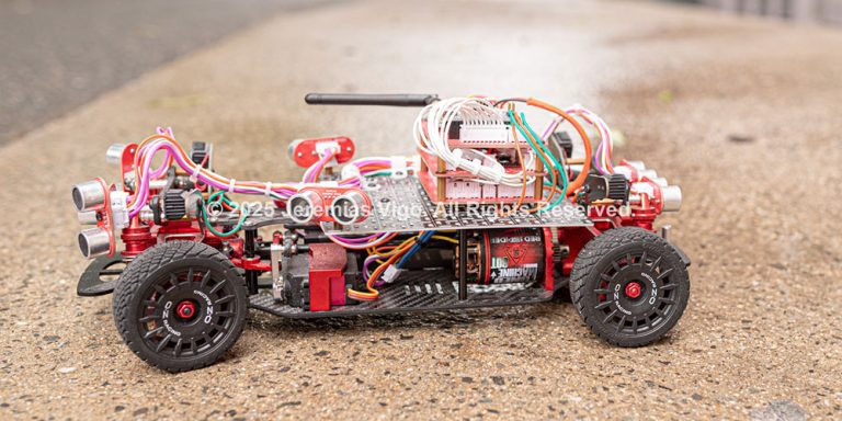
Many of us may relate the concept of remote-control car to the toy industry. However, it is important to know that these remotely operated devices can also be applied to high-end projects. Such projects are not only limited to cars but drones, rovers, robots, and more. Technology is advancing everyday and the demand for these automated systems is also increasing.
When we go back to last semester’s project, we realize how much progress we have made so far. From planning just an update to the previous car, we ended up building a much more advanced model. Despite using similar mechanical concepts, these two projects differ from each other in terms of technology and design. Moving from a “light-sensing” infrared system to an ultrasonic system has opened up a whole new world of possibilities. Each successful project gives us the confidence we need and makes us realize that we are capable of doing whatever we set our minds to.
As with any project, there is always something that doesn’t go as planned. There is always that little detail that needs to be fixed. Although we have successfully achieved what we primarily planned, the project presents some flaws that we plan to correct in the future. One drawback we found about this car is that its ultrasonic collision assist doesn’t help much when it comes to higher speeds. This could be fixed by updating the code so that it can adjust the detection distance according to the speed of the car. Unfortunately, this is something we haven’t had time to work on yet. Another drawback we found is that despite having a good number of sensors, the car still has difficulty detecting some objects depending on the angle. This could also be solved by adding at least two more sensors to the front of the car at a 20o degrees angle. These are definitely things we can take into account when planning our future projects.

REFERENCES
- Alexander, Charles K., Sadiku, Matthew N. O. Fundamentals of Electric Circuits — Sixth edition, Published by McGraw-Hill Education, New York, 2017
- CodeCogs LaTeX/Mathematics Equation Editor. Zyba Ltd ©, 2004-2024, https://editor.codecogs.com/
- KiCad EDA. Schematic Capture & PCB Design Software, KiCad Developers Team, 1992-2024, https://www.kicad.org/
- Pololu Robotics and Electronics. TB6612FNG dual motor driver carrier. 2001–2024 Pololu Corporation. https://www.pololu.com/product/713