The consequences of dirty energy sources on the global environment have become a matter of major concern in today’s society. For decades, humanity has been facing great challenges caused by the lack of clean energy. Radioactive and chemical waste are being buried in our soil, while burning fuel pollution is being released into our atmosphere. This is extremely harmful to human health. We recognize the rapid advancement of technology as the primary cause of all these issues. However, it is important to acknowledge that the same technological advancements have the potential to serve as practical solutions to these pressing problems. Therefore, the main purpose of this project is to address the problem caused by the usage of dirty energy within the toy industry—more specifically RC cars. And it will do this by utilizing clean and efficient energy (solar energy) as its primary power source. For many decades, “battery powered toys” have been used and no one seems to be doing anything to change that. The problem with this is that these batteries are made with minerals extracted from underground and processed into dangerous chemicals. The manufacturing process produces CO2 and a great amount of these chemical compounds are emitted into the air. Solar energy, however, has no environmental impact and is considered one of the cleanest sources of energy today.
Unfortunately, solar energy is not always there when we need it. Solar panels usually rely on a great amount of light to produce power. So for most applications we’ll need a secondary source of energy to ensure the system’s operation at all times. We’ll also need a system that is capable of storing energy and that could be used as a backup source of power as needed. So, for the purpose of this project, a rechargeable battery will be utilized. The battery will not only be able to store energy for the “rainy day,” but also will provide power to the system when it’s dark. However, there is a major problem that arises with this type of project. A system that responds accordingly to different light conditions involves a technology that would automatically decide which power source to use —which would be capable of switching from one source to the other without interrupting the system’s operation. And this is one interesting thing about this project.
GENERAL DESCRIPTION OF THE SYSTEM
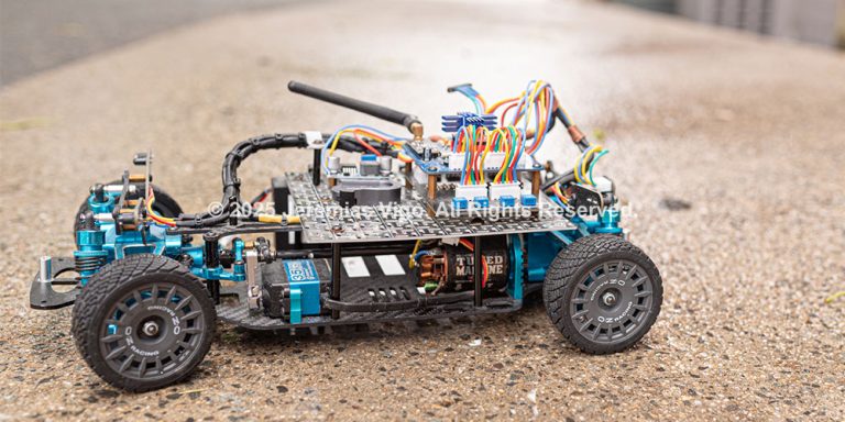
This design project utilizes solar energy as its primary power source for the system’s operation. It integrates an intelligent dark mode technology which makes it possible to operate in the dark —by using a rechargeable battery as a backup source of energy. It also features a remote control (Appendix H, figure 20) that allows precise communications and control from a distance. This project combines solar and battery power to optimize efficiency and enhance overall performance.
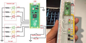
The system consists of two main sections: the transmitter (remote control) and the receiver (car). The transmitter (Appendix E, figure 3) uses an Arduino Nano and an RF transceiver module (NRF24L01) to communicate with the receiver. Although the transmitter operates at a voltage of 5 volts, the voltage of the receiver is stepped down from its double power sources and regulated to 7.5 volts. The receiver (Appendix D, figure 2) utilizes the same microcontroller and RF module to receive and interpret commands from the transmitter into electrical current necessary for the system’s operation. The working frequency between the transmitter and the receiver is 2.4 GHz and can reach up to 800 meters —in the maximum PA. The receiver has the ability to automatically switch between solar and battery power based on light condition, using what’s called “Intelligent Dark Mode Power Switch” (IDMPS).

The system also integrates an experimental obstacle avoidance system, which for the purpose of this project we called the Infrared (IR) Collision Assistance. This system was integrated into this project with the main goal of adding an extra layer of protection to the car. It’s important to notice that this is in an experimental phase and does not guarantee full protection to the car.
THE INTELLIGENT DARK MODE POWER SWITCH (IDMPS)
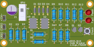
The IDMPS is a section located in the receiver’s main board and consists of several components. It is responsible to automatically select between battery and solar power to ensure the system’s operation at all times. The system includes a solar panel measuring 26 x 25 inches which is attached to the top of the car (Appendix H, figure 19). It produces an output power of around 12W when operating at full capacity. The output voltage ranges around ~12 volts with a current of ~1.6 amps (after step down). This output is stepped down to 7.5 volts to meet the system’s voltage requirement. The battery is recharged by solar power as long as there is enough light for the system’s operation. In the event when there is insufficient light, the IDMPS will activate, and the system will be powered by the backup battery instead. This happens when the light dependent resistor (LDR) doesn’t detect enough light causing the IC (LM555) to turn the relay off, switching it from “solar” to the “backup battery” position. The IDMPS will function as a “light dependent switcher” responsible for automatically deciding between battery and solar power—without the need of manual input.
Here’s a brief summary of how the will IDMPS operate:
- The battery will recharge with solar energy when there is enough light. When there is insufficient light, however, the IDMPS will activate, and the system will be powered by the backup battery instead. This happens when the LDR doesn’t detect enough light causing the LM555 to turn the relay off, switching it from “solar” to the “backup battery” position.
- A potentiometer (R2) of 5KΩ is used to adjust the light threshold for the IDMPS. R2 works in conjunction with the LDR (R1) and adjusts the output voltage (Vout) that triggers the LM555 (Appendix A, figure 1), which consequently activates the relay (K1). The potentiometer is manually adjusted to determine the light intensity desired to activate solar power.
- Finally, the LED1 (green) and LED2 (red) will indicate whether the system is operating using solar or battery power (Appendix H, figure 18).
Finding the resistance value for R2:
- With the help of a multimeter, we measured the resistance values of the LDR in different light situations. We found that when light falls in it the resistance varies from 450-800Ω. When there is no light, however, its resistance rises over 800Ω.
| Light | Dark | |
| R1 LDR (Ohms) | 450–800Ω | > 800Ω |
| Vout (Volts) | > 5.1V | < 5.1V |
| Vin (Volts) | 7.5V | 7.5V |
- To find the correct value for R2 we applied the formula
with the borderline voltage for Vout being 5.1V (this is the reset voltage for the NE555 timer that we needed to trigger the relay). However, because R1 resistance ranged from 450-800Ω depending on the intensity of light, we applied the formula for both values.
| First value | |
| Second value |
- We found that the value of R2 would vary from 956Ω to about 1.7KΩ, so the best option would be to use a 2KΩ potentiometer. However, we ended up using a potentiometer of 5K—as it was the closest value we had available—and that did the job just well.
THE INFRARED (IR) COLLISION ASSISTANCE
The Infrared (IR) Collision Assistance (Appendix F, figure 4) has four distinct channels which are responsible for each of the four corners of the car (front-right, front-left, rear-right, rear-left), consisting of four IR sensors and a control board. Each IR channel integrates a LM358 Dual Operational Amplifier IC which operates in conjunction with an infrared light-emitting diode (IR LED) and a photodiode to receive any obstacle reflected infrared light. Each circuit also includes three resistors and a potentiometer which adjusts the sensitivity and the desired obstacle distance for each channel.

The system generates high (1) and low (0) output depending on whether an obstacle is in the sensor’s range or not. When an obstacle is detected by one of the channels, it activates pin 3 (input) of the LM358. This produces a high output on pin 1, which subsequently triggers the appropriate Arduino input, causing an immediate action to be taken. This applies to any of the four IR channels, noting that each of these channels can be adjusted independently and have a completely different response.
THE ARDUINO AND ITS WIRELESS COMMUNICATION
The Arduino platform has become widely used in fields such as robotics, IoT, wearable tech, and home automation. Its large community of developers and enthusiasts contributes to its popularity. Also, its affordability and versatility have revolutionized electronics and programming, making projects like this one possible.
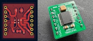
In our project, we utilized a third-party Arduino Nano version 3, due to its compact size and powerful microcontroller capabilities based on the ATmega328p. This model consists of 14 digital I/O pins and 8 analog inputs (that can also be used as digital inputs), which is more than enough for our project. The nano version is also perfect for projects that require small form factors and low power consumption—which is one of the main reasons we chose to use it. In addition, we used two nRF24L01 which in combination with the Arduino allowed for wireless communication between the transmitter and the receiver boards. The nRF24L01 is a 2.4 GHz transceiver module that enables wireless communication between devices over short distances. In our project, it is responsible for all communication between the transmitter (Tx) and the receiver (Rx).
In the transmitter, which is located in the remote control, the Arduino is programmed to collect data from both right and left joysticks and send them through wireless using the nRF24L01 module. The transmitting Arduino sends data packets, which are received by the receiving Arduino, processed, and responded to accordingly. On the receiver side, another nRF24L01 module is set up to receive the joystick commands sent from the transmitter. The receiving Arduino then decodes the incoming radio signals and extracts the data sent by the transmitter. This data is then processed and used to trigger a specific action based on the command received.
DESIGN RELATED PROBLEMS AND SOLUTIONS
Situation 1. On March 16, the first version (version 1.01) of our remote-controlled car was released. Along with it, an integrity test was performed with the purpose of identifying problems with the main board’s electrical wiring. The test was carefully carried out by the electrical engineering students of our team. It performed well with no issues in most parts; however, two major problems were found, which we are currently working to address as soon as possible. Both problems were related to the IDMPS, which is the section located in the receiver’s main board and responsible for automatically switching between power sources—based on the current light condition. Following are the major problems encountered along our testing:
- The first problem that was identified during the test was related to the behavior of the switch section of the IDMPS. We noticed that the relay (K1) was not working correctly and was operating in the opposite direction—activating the backup battery when there was light and the solar power when it was dark. To find out what the error was, we first referred to the relay’s manufacturer datasheet. We then used a multimeter to check the PCB for any inverted connections but could not find anything wrong. However, further research and testing indicated that the circuit we designed was a dark sensor rather than a light activating switch. We tried tweaking the connections to make it function the other way around but ended up burning the whole board. So we had no other option but to redesign a whole new circuit diagram—this included all calculations necessary to find the values of the new components. Once we concluded the circuit design diagram, we used a breadboard to test everything and make sure everything worked before ordering the new PCB (Appendix G, figure 5 & 6).
- As we were testing the new circuit on the breadboard, we identified a second problem. We found that the potentiometer used to set the light threshold was too sensitive and would not adjust precisely. The potentiometer (R2) works in conjunction with the LDR (R1) and adjusts the output voltage (Vout) that triggers the LM555, which consequently activates the relay (K1). R2 has to be manually adjusted to determine the light intensity required to activate the solar power. But the problem was that the relay was only activated when the light was extremely high (higher than the sunlight). We came to the conclusion that the R2’s resistance of the 10KΩ was way higher than we needed. So we used the formula
Situation 2. On April 26, the team met in person for the last time. The meeting lasted about 3 hours. The main purpose of the meeting was to perform a project upgrade adding the Infrared (IR) Collision Assistance while the car is controlled. Before proceeding with the upgrade, the team ran a quick test on the car. This was done to make sure everything was working as it should before moving further with the upgrade. We tested the forward and backward throttle, the direction, and also the IDMPS by simulating the switch between battery and solar power. The car responded and behaved as it should.
After that, we worked on adding the IR collision assistance board and sensors. The new board (Appendix G, figure 9-12) was designed accordingly such that it would fit exactly under the receiver’s main board. The receiver’s main board was moved in a way it would stand on top of the IR board. The team carefully soldered the components and the connectors on the new board, as well as the sensors on the small boards which act as obstacle’s detectors. After installing the first sensor (front-left), and updated the code, we tested it to see how it would behave in real life situations. At first everything seemed to be working as expected as it responded to our hand gestures. We changed the sensitivity of the sensor to detect an obstacle from a distance of about 6 inches. As we tested on the ground the sensor also reacted to obstacles on the left and responded by turning the servo motor to the right. We installed the second sensor (front-right) and tested it once again. This time the car avoided obstacles from both sides and when the obstacle blocked both sensors at the same time, the car stopped—this was done by adding conditional statements to the code (as seen in Appendix J). The other two sensors in the back were also installed and tested perfectly. However, we ran into two problems: one which was easily fixed and the other one we’ll probably have to live with until we come up with a good solution.
- The first issue we ran into was the inability to control the car after an object was detected by the two pairs of sensors simultaneously (front left/right and rear left/right). Every time an emergency stop occurred the car became completely unresponsive, and we had to move it with our hands in order to regain control of the car. This happened due to an incomplete conditional statement on Arduino’s code. When both left and right sensors are triggered by an object, they send high output to the Arduino’s inputs (14, 15, 16 and 17) and because of an “if statement” error it was overwriting the joysticks commands. The problem was eventually addressed by replacing the conditional statements with a fresh one.
- The second issue we ran into was detected on the following day. As we tested the car outside in a bright light, the IR system didn’t behave as well as it should. The sensors became very sensitive and were reacting to the daylight, so we had to unplug the cables from the IR board, so it didn’t interfere with the normal operation of the car. We later found that the sensitivity could be adjusted by increasing or decreasing the resistance of the potentiometers while outdoors. However, having to adjust sensitivity every time a change in light occurs would be very inconvenient. Therefore, the team recognized the limitation of using infrared systems and concluded that, for future versions, we should instead consider using ultrasonic sensors. That way we would ensure the sensors would work in any light condition.
CONCLUSION
The main purpose of this project is to address the issues arising from the utilization of dirty energy sources in the toy industry, more specifically RC cars. It addresses this concern by using solar energy as the primary power source. The system has an Intelligent Dark-Mode Power Switch, also known as IDMPS, which guarantees continuous operation regardless of light condition. It does this by detecting the amount of light available and automatically switching between solar and battery power. The system is composed of a transmitter and a receiver, both utilizing Arduino and RF modules for wireless communication. Additionally, the system integrates an experimental obstacle avoidance system (Infrared Collision Assistance) which adds a layer of protection to the car.
Despite being an experimental design, there are some facts about this project that differentiate it from similar models out there. If we search on the internet, we can easily find a variety of different RC car models, with all kinds of shapes and technologies. However, the one thing that distinguishes this project from those we find on the internet is its capacity to operate in different light conditions while being primarily powered by solar energy. Another unique feature is its capacity to automatically determine which power source to use—whether solar or battery— based on certain conditions, which is only possible due to its built-in Intelligent Dark-Mode Power Switch (IDMPS). In future upgrades, this model can be modified to be used in a wider range of applications. Such upgrades would be mainly focused on power efficiency through incorporation of latest technologies, such as more efficient solar panels—which can produce more power while using less space. It would also include an intelligent shutdown for energy conservation, turning down the system when the car stops, while directing all power to the backup battery for recharging purposes. However, this would be a topic for the next design project.


LIST OF MATERIALS
Below are all the materials used to carry out the project along with the corresponding links to the suppliers where they were purchased: