Overview
This project is a compact embedded-systems build that models a real intersection controller: car traffic and pedestrians each have a red/yellow/green signal, and a pedestrian can request a crossing using a button. I built the hardware on a breadboard using a Raspberry Pi Pico 2 and wrote the control logic in ARM Cortex-M0+ assembly, using simple GPIO helper routines and millisecond sleep calls.
The goal was to keep the circuit minimal but make the behavior realistic: predictable timing, safe transitions (both red), and responsive buttons through debouncing and frequent input polling. The design comes the following features:
- Car signal cycle: Green → Yellow → Red
- Pedestrian signal cycle: Green → Yellow → Red
- Pedestrian request button: latched request that is serviced safely (no abrupt phase flips)
- Power/Start button: toggles the entire system between running and all off
- Safe transition: both directions red before switching right-of-way
- Button debouncing: simple 20 ms confirm + (for power) release-wait
Hardware
Parts:
- Raspberry Pi Pico 2
- 6× LEDs (2× Red, 2× Yellow, 2× Green)
- 6× current-limiting resistors (typical 220–1kΩ)
- 2× momentary pushbuttons (Power SW + Ped Request)
- Breadboard + jumper wires
GPIO map:
| Function | GPIO |
|---|---|
| Car Green / Yellow / Red | GP13 / GP14 / GP15 |
| Ped Green / Yellow / Red | GP10 / GP11 / GP12 |
| Pedestrian Request Button | GP16 |
| Power/Start Button | GP17 |
Note: Both buttons are active-low (pressed reads 0), meaning the input is normally pulled up and goes to GND when pressed.
Build photos & diagram:
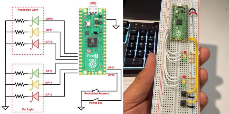
Figure 1 shows the full pin mapping and how each LED and button ties back to the Pico 2. I kept the layout intentionally simple: six GPIO outputs for the lights and two GPIO inputs for the controls.

Figure 1 – Wiring diagram (GPIO assignments)
Figure 2 is the working hardware build I used for testing the state machine in assembly. The LEDs are grouped by function (car vs. pedestrian), with the buttons placed low on the board for easy interaction during timing tests.
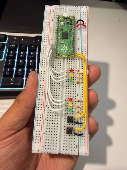
Figure 2 – Breadboard prototype (Pico 2 + LEDs + buttons)
Traffic Light Controller Demo:
In Video 1, I walk through the full sequence and show how the pedestrian request interrupts the normal cycle in a controlled (safe) way. You can also see that button input remains responsive because the firmware checks inputs frequently instead of using one long blocking delay.
Video 1. Demonstration of the Raspberry Pi Pico 2 traffic light controller running on a breadboard. The controller cycles the car signal and pedestrian signal through green/yellow/red timing, while continuously monitoring the Power/Start button and the Pedestrian Request button. When a pedestrian request is pressed, the system safely completes the current phase, transitions through yellow, enforces a both-red safety window, and then services the pedestrian crossing before returning to the normal cycle.
Software approach (assembly “state machine”)
Even though this is assembly, the logic is structured like a clean finite-state controller. I use three flags in .data:
running_flag— system enabled/disabled (toggled by Power SW)ped_flag— pedestrian request latched (set by Ped button)ped_active— blocks new requests while pedestrian phase is being served
Main loop behavior:
- Check the Power SW (toggle run/stop)
- If stopped: force everything off (
all_off) - If running:
- Force Ped = Red, run Car cycle
- Force Car = Red, run Ped cycle
- Repeat
This keeps the behavior stable and predictable, while still allowing the pedestrian request to interrupt at safe points.
Timing and responsiveness:
Instead of using one long “blocking delay,” the code waits in 10 ms chunks and checks inputs repeatedly. That makes the system feel responsive even during a long green phase.
From the constants in my assembly:
- Green duration: ~10 s
- Yellow duration: ~3 s
- All-red safety transition: ~1 s
Pedestrian request logic:
When the pedestrian button is pressed:
- the request is latched (
ped_flag = 1) - the controller finishes the current step safely:
- transitions through yellow
- then goes to both red
- then services the pedestrian sequence
- the request flag is cleared after it’s handled
This is the same principle used in real traffic controllers: requests are acknowledged, but right-of-way changes only happen at safe transition points.
Code (high-level structure):
I’m including my assembly below as the core deliverable for this project. The important routines are:
traffic_light_run— main control loopcheck_powerSW— toggles running state with debounce + release-waitcheck_ped_button— latches pedestrian request (debounced)phase_wait— green-phase wait with frequent input pollingyellow_full_duration— timed yellow/red windows that still allow power checksboth_redandall_off— safety and shutdown statesset_cycle_common— reusable cycle logic (green → yellow → red)set1_cycle/set2_cycle— wrappers for car vs pedestrian signals
Results
This build behaves cleanly and reliably:
- No flickering or ambiguous LED states
- Pedestrian requests are serviced safely
- The controller can be stopped at any time (everything turns off)
- Buttons feel responsive thanks to frequent polling and debouncing
It was also a great exercise in writing structured firmware in assembly—using flags, subroutines, and state transitions instead of a single giant loop.
Future Improvement
If I iterate on this project, I’d like to add:
- A real WALK interval (ped green held for N seconds)
- A flashing DON’T WALK phase (ped yellow blink)
- Timer interrupts instead of
sleep_msfor a more “RTOS-like” design - UART logging for debugging state transitions in real time
References
- Raspberry Pi Pico SDK Documentation
https://datasheets.raspberrypi.com/pico/raspberry-pi-pico-c-sdk.pdf - Raspberry Pi Pico Datasheet
https://datasheets.raspberrypi.com/pico/pico-datasheet.pdf - RP2040 ARM Cortex-M0+ Processor Documentation
https://developer.arm.com/documentation/ddi0432/c/ - General Debouncing Guide (SparkFun)
https://learn.sparkfun.com/tutorials/button-and-switch-basics/all - State Machine Design Overview
https://www.geeksforgeeks.org/introduction-of-finite-automata/